The following content is the lab assignment report for course WIX1003 - Computer Systems & Organization, Universiti Malaya, in which we are required to do a Pedestrian Light Simulation using MCU8051.
The PDF version report can be found here. Or you can view the report in in the bottom of this page by clicking here.
Pedestrian Lights Simulation using MCU8051
Component connection diagram
Complete code of system with an explanation on the operation
1 | ;ped lights |
Design Consideration
Analyzing
To make it easier to discuss, we name the lights by their position. North, West, South, and East.
In analyzing the requirements, we find that among four lights, there are always 3 red lights and 1 green/yellow light so we divide its process into 4 states.
State1: North changes from green to yellow. West, South, and East are red.
State2: West changes from green to yellow. North, South, and East are red.
State3: South changes from green to yellow. North, West, and East are red.
State4: East changes from green to yellow. North, West, and South are red.
In the next state after state4, it comes back to state1.
Displaying lights
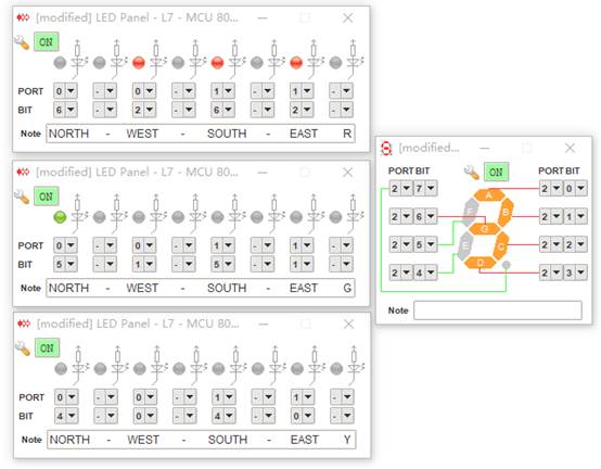
Every light has three colors, so we use one digit from port to represent each color, and use 1/0 to represent if they are on or off now.
For each port has 2 digits in hexadecimal, we believe it will be clearer if we use one hexadecimal digit of each port to represent one light. And we intentionally leave one bit of the digit invalid.
We assign p0 to North and West, p1 to South and East in the following order
– p0.7 North - Invalid
– p0.6 North - Red
– p0.5 North - Green
– p0.4 North - Yellow
– p0.3 West - Invalid
– p0.2 West - Red
– p0.1 West - Green
– p0.0 West - Yellow
– p1.7 South - Invalid
– p1.6 South - Red
– p1.5 South - Green
– p1.4 South - Yellow
– p1.3 East - Invalid
– p1.2 East - Red
– p1.1 East - Green
– p1.0 East - Yellow
For the display of hexadecimal digits.
B (or 1011) means the light this hexadecimal digit represents is displaying Red.
D (or 1101) means the light this hexadecimal digit represents is displaying Green.
E (or 1110) means the light this hexadecimal digit represents is displaying Yellow.
Displaying countdown digits
We store 7-segment display pattern from 0-9 to the lookup table and use a subroutine to perform countdown. We use port 2 to display 7-segment digit.
Before calling countdown subroutine, we need to assign the countdown time to B.
In the subroutine, we first move B to A and check if A equals to 0, if not, we load value from the lookup table, display the segment number, call a one-second delay, decrease B by one and SJMP to countdown subroutine. If A equals 0, it will return.
Coding
In Main, we set p0, p1, p2 as output and move table address to Data Pointer.
In Start, we reset the lights and 7-segment display.
After start, we straightly go to state1.
Inside each state, we will first set the state of 4 lights, one green three red, and then we assign 9 to B and call the count to execute the countdown of green light from 9 to 1. Then we set the green light to yellow, then we assign 3 to B and call the count to execute the countdown of yellow light from 3 to 1.
In the end of each state, we SJMP to next state.
System Limitation
i. The countdown can only display 1- digit number
The system doesn’t display count down number for all 4 lights, instead, it counts down for the one light of all four lights which is not red.To change the time duration of red, green, or yellow light, we need to change in four different places.